Some time ago, Alex Beregszaszi and I created an FFmpeg video decoder to handle Duck TrueMotion 1 data. However, there are two major variations of this data format: 16-bit and 24-bit. The FFmpeg decoder presently only handles 16-bit data. There is a non-negligible number of games from the mid- to late-1990s that used this format for their FMV and many of them use the 24-bit variant.

Virtua Cop 2, Sega Saturn,
one of the Duck TM1-using games that uses the 16-bit variant
Duck TM1 was one of the formats that first piqued my curiosity in multimedia hacking. I found some AVI files while exploring some Sega Saturn CD-ROM titles. I found some Japanese Win32 programs that knew how to decode the format and I tried hard to reverse engineer them. Eventually, Alex tipped me off that On2 had released the decoder as part of their VpVision source package. Just another case for making sure you have exhausted all other avenues before attempting to reverse engineer something.
In addition to the 16- and 24-bit modes, it is also worth noting that Duck’s original source code indicates that the TM1 codec also supports some kind of sprite modes. It is not known whether this was ever used. Further, the source code makes mention of Sony PlayStation 1 support so the format may be found on some original PS games (there must be thousands of titles to choose from by now).
Kostya’s blog and his recent work on Duck TrueMotion 2 reminded me that these blogs are good for thinking [typing] out loud while working through problems. I have had a work-in-progress description of the Duck TM1 decoder for a long time. But just in case someone else feels inspired to work on the FFmpeg TM1 decoder again soon, I thought I would do my best to explain how the algorithm works.
First thing’s first, here are some 24-bit Duck TM1-encoded AVI files from different games:
http://samples.mplayerhq.hu/V-codecs/DUCK/
The philosophy of TM1 is similar to TM2 (actually, it is more appropriate to say TM2 is similar to TM1). It is all prediction based (with some interframe differencing thrown in for when the data is unchanged). For this codec, the prediction operates in both the vertical and horizontal directions. A delta is decoded from the encoded data stream and applied to both the left pixel and the up pixel to form the new pixel.
In the case of 16-bit TM1 data, the output data is formatted as RGB555. The data is not decoded 1 pixel at a time but rather 2 pixels at a time. The codec was designed to take advantage of 32-bit processors and their 32-bit general-purpose registers and as such applies a pair of deltas to a pair of pixel predictors.
The 16-bit variant TM1 bytestream (yes bytes, no bit parsing or VLCs required) is primarily comprised of a series of bytes that index into a 256-element table. A table element contains between 1 and 4 32-bit deltas. Each 32-bit number is a pair of 16-bit pixel predictors. At the start of each row, the left predictor is cleared. Fetch the first byte from the bytestream and index into the table. Apply that delta to the predictor (last pair of pixels). Use up the remaining delta pairs in the selected table element before fetching a new table index from the bytestream.
Where do the delta tables come from? Fundamentally, there are various combinations of tables that are generated and selected based on the overly-long and quasi-encrypted frame header. There are actually four tables generated: Skinny Y deltas, fat Y deltas, skinny C deltas, and fat C deltas. The ‘Y’ and ‘C’ roughly correspond to the concepts of luminance (Y) data and chrominance (U & V/Cb & Cr) data in traditional YUV/YCbCr colorspaces in that the Y deltas are more important and applied more frequently than the C deltas. The skinny deltas are relatively small while the fat deltas are larger. The default behavior is to decode an index byte from the encoded bytestream and if the index is 0, fetch another index and use it to index into the fat delta table vs. the skinny delta table.
As is customary in YUV coding schemes, the C components (U and V) do not get as much information as the Y components. TM1 is no exception. A TM1 frame is comprised of a series of 4×4 blocks (16 pixels; 8 pixel pairs; 4 rows of 2 pixel pairs). Each pixel has a Y delta applied to it. But not every pixel has a C delta. The frame header selects the blocking mode: 4×4, 4×2, 2×4, 2×2. The mode specifies how often the C delta is applied. In a 4×4 block, the C delta is applied only once, on the first pixel predictor (proceeding from left -> right, top -> bottom):
(apply C) (apply Y & output pixel pair) (apply Y & output pixel pair)
          (apply Y & output pixel pair) (apply Y & output pixel pair)
          (apply Y & output pixel pair) (apply Y & output pixel pair)
          (apply Y & output pixel pair) (apply Y & output pixel pair)
In the 4×2 mode, a 4×4 block is broken into 2 4×2 blocks. The C delta is applied at the start of each of these blocks:
(apply C) (apply Y & output pixel pair) (apply Y & output pixel pair)
          (apply Y & output pixel pair) (apply Y & output pixel pair)
(apply C) (apply Y & output pixel pair) (apply Y & output pixel pair)
          (apply Y & output pixel pair) (apply Y & output pixel pair)
Are you beginning to see the pattern here? Here is the sequence for the 2×4 mode:
(apply C) (apply Y & output pixel pair) (apply C) (apply Y & output pixel pair)
          (apply Y & output pixel pair)           (apply Y & output pixel pair)
          (apply Y & output pixel pair)           (apply Y & output pixel pair)
          (apply Y & output pixel pair)           (apply Y & output pixel pair)
And for the 2×2 mode:
(apply C) (apply Y & output pixel pair) (apply C) (apply Y & output pixel pair)
          (apply Y & output pixel pair)           (apply Y & output pixel pair)
(apply C) (apply Y & output pixel pair) (apply C) (apply Y & output pixel pair)
          (apply Y & output pixel pair)           (apply Y & output pixel pair)
TM1 also employs frame differencing. An encoded chunk of data contains a series of change bits that indicate whether a particular 4×4 block has changed since the previous frame.
This brings us to the 24-bit variant. FFmpeg’s TM1 decoder does not handle this correctly yet as we have not worked out all the finer details for decoding. This is the typical result right now:
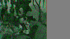
Sonic 3D Blast, sort of…
this is a 24-bit TM1 sample
As you can see, the right 1/3 of the frame is not painted. This makes a little sense when considering that the output data is supposed to be 24-bit and the incomplete code is still outputting 16-bit data.
Is all of that clear? Yes? Excellent. If you feel inspired, go ahead and try your hand at understanding the 24-bit variant. The original source code for the Duck TM1 and TM2 decoders is contained in the VpVision package found here: