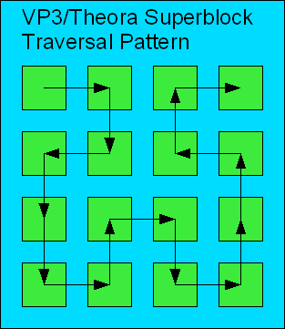
Hands down, one of the hardest parts about the VP3/Theora coding method is the bizarre fragment traversal pattern. Most everything else that VP3 does is seen in other codecs. But the Hilbert pattern used for encoding and decoding coefficients creates a monster. Vector drawing program to the rescue!
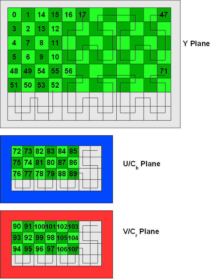
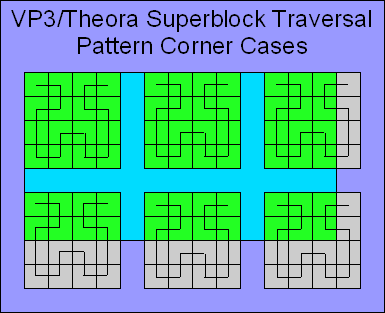
Imagine a video frame with a resolution of 96×48, highly contrived for this example. The Y plane would consist of 12×6 fragments (8×8 block of samples). Meanwhile, the U and V planes would each consist of 6×3 fragments. Recall that VP3 employs a notion of a superblock, which encompasses a group of 4×4 fragments. If the fragment resolution of a plane is not divisible by 4, the plane must be conceptually padded out to the nearest superblock boundary for the traversal pattern.
click on the image for the full sized image

The above drawing illustrates the order that the fragments are traversed in our hypothetical 96×48 frame when decoding coefficients. Note, in particular, the strange order in which fragments 50..53 are traversed.
I hope that’s clear enough. The challenge at hand is to establish data structures at the start of the encode or decode process. Generally, you will allocate an array of fragment data structures: Fragment indices 0, 1, 2, 3, etc. will proceed left -> right, then top to bottom. The second row of the Y plane begins at index 12, third row at index 24, and so on. But when it comes to decoding the DCT coefficients, it is necessary to traverse through the fragment data structure array at indices 0, 1, 13, 12, 24, 36, 37, 25, and so on. Thus, it is customary to build an array that maps one set of indices to the other. I’m having flashbacks just thinking about it. I remember developing a completely different algorithm than the official VP3 decoder when I reimplemented the decoder for FFmpeg.
Oh yeah, and remember that all VP3/Theora decoding is performed upside-down. I choose not to illustrate that fact in these drawings since this stuff is complicated enough.

