Early last month, this thing called ORBX.js was in the news. It ostensibly has something to do with streaming video and codec technology, which naturally catches my interest. The hype was kicked off by Mozilla honcho Brendan Eich when he posted an article asserting that HD video decoding could be entirely performed in JavaScript. We’ve seen this kind of thing before using Broadway– an H.264 decoder implemented entirely in JS. But that exposes some very obvious limitations (notably CPU usage).
But this new video codec promises 1080p HD playback directly in JavaScript which is a lofty claim. How could it possibly do this? I got the impression that performance was achieved using WebGL, an extension which allows JavaScript access to accelerated 3D graphics hardware. Browsing through the conversations surrounding the ORBX.js announcement, I found this confirmation from Eich himself:
You’re right that WebGL does heavy lifting.
As of this writing, ORBX.js remains some kind of private tech demo. If there were a public demo available, it would necessarily be easy to reverse engineer the downloadable JavaScript decoder.
But the announcement was enough to make me wonder how it could be possible to create a video codec which effectively leverages 3D hardware.
Prior Art
In theorizing about this, it continually occurs to me that I can’t possibly be the first person to attempt to do this (or the ORBX.js people, for that matter). In googling on the matter, I found various forums and Q&A posts where people asked if it were possible to, e.g., accelerate JPEG decoding and presentation using 3D hardware, with no answers. I also found a blog post which describes a plan to use 3D hardware to accelerate VP8 video decoding. It was a project done under the banner of Google’s Summer of Code in 2011, though I’m not sure which open source group mentored the effort. The project did not end up producing the shader-based VP8 codec originally chartered but mentions that “The ‘client side’ of the VP8 VDPAU implementation is working and is currently being reviewed by the libvdpau maintainers.” I’m not sure what that means. Perhaps it includes modifications to the public API that supports VP8, but is waiting for the underlying hardware to actually implement VP8 decoding blocks in hardware.
What’s So Hard About This?
Video decoding is a computationally intensive task. GPUs are known to be really awesome at chewing through computationally intensive tasks. So why aren’t GPUs a natural fit for decoding video codecs?
Generally, it boils down to parallelism, or lack of opportunities thereof. GPUs are really good at doing the exact same operations over lots of data at once. The problem is that decoding compressed video usually requires multiple phases that cannot be parallelized, and the individual phases often cannot be parallelized. In strictly mathematical terms, a compressed data stream will need to be decoded by applying a function f(x) over each data element, x0 .. xn. However, the function relies on having applied the function to the previous data element, i.e.:
f(xn) = f(f(xn-1))
What happens when you try to parallelize such an algorithm? Temporal rifts in the space/time continuum, if you’re in a Star Trek episode. If you’re in the real world, you’ll get incorrect, unusuable data as the parallel computation is seeded with a bunch of invalid data at multiple points (which is illustrated in some of the pictures in the aforementioned blog post about accelerated VP8).
Example: JPEG
Let’s take a very general look at the various stages involved in decoding the ubiquitous JPEG format:
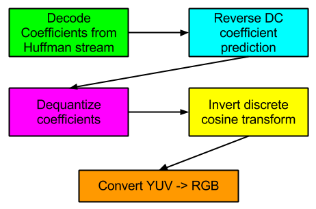
What are the opportunities to parallelize these various phases?
- Huffman decoding (run length decoding and zig-zag reordering is assumed to be rolled into this phase): not many opportunities for parallelizing the various Huffman formats out there, including this one. Decoding most Huffman streams is necessarily a sequential operation. I once hypothesized that it would be possible to engineer a codec to achieve some parallelism during the entropy decoding phase, and later found that On2’s VP8 codec employs the scheme. However, such a scheme is unlikely to break down to such a fine level that WebGL would require.
- Reverse DC prediction: JPEG — and many other codecs — doesn’t store full DC coefficients. It stores differences in successive DC coefficients. Reversing this process can’t be parallelized. See the discussion in the previous section.
- Dequantize coefficients: This could be very parallelized. It should be noted that software decoders often don’t dequantize all coefficients. Many coefficients are 0 and it’s a waste of a multiplication operation to dequantize. Thus, this phase is sometimes rolled into the Huffman decoding phase.
- Invert discrete cosine transform: This seems like it could be highly parallelizable. I will be exploring this further in this post.
- Convert YUV -> RGB for final display: This is a well-established use case for 3D acceleration.
Crash Course in 3D Shaders and Humility
So I wanted to see if I could accelerate some parts of JPEG decoding using something called shaders. I made an effort to understand 3D programming and its associated math throughout the 1990s but 3D technology left me behind a very long time ago while I got mixed up in this multimedia stuff. So I plowed through a few books concerning WebGL (thanks to my new Safari Books Online subscription). After I learned enough about WebGL/JS to be dangerous and just enough about shader programming to be absolutely lethal, I set out to try my hand at optimizing IDCT using shaders.
Here’s my extremely high level (and probably hopelessly naive) view of the modern GPU shader programming model:
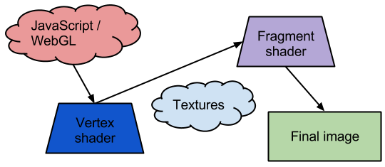
The WebGL program written in JavaScript drives the show. It sends a set of vertices into the WebGL system and each vertex is processed through a vertex shader. Then, each pixel that falls within a set of vertices is sent through a fragment shader to compute the final pixel attributes (R, G, B, and alpha value). Another consideration is textures: This is data that the program uploads to GPU memory which can be accessed programmatically by the shaders).
These shaders (vertex and fragment) are key to the GPU’s programmability. How are they programmed? Using a special C-like shading language. Thought I: “C-like language? I know C! I should be able to master this in short order!” So I charged forward with my assumptions and proceeded to get smacked down repeatedly by the overall programming paradigm. I came to recognize this as a variation of the scientific method: Develop a hypothesis– in my case, a mental model of how the system works; develop an experiment (short program) to prove or disprove the model; realize something fundamental that I was overlooking; formulate new hypothesis and repeat.
First Approach: Vertex Workhorse
My first pitch goes like this:
- Upload DCT coefficients to GPU memory in the form of textures
- Program a vertex mesh that encapsulates 16×16 macroblocks
- Distribute the IDCT effort among multiple vertex shaders
- Pass transformed Y, U, and V blocks to fragment shader which will convert the samples to RGB
So the idea is that decoding of 16×16 macroblocks is parallelized. A macroblock embodies 6 blocks:

It would be nice to process one of these 6 blocks in each vertex. But that means drawing a square with 6 vertices. How do you do that? I eventually realized that drawing a square with 6 vertices is the recommended method for drawing a square on 3D hardware. Using 2 triangles, each with 3 vertices (0, 1, 2; 3, 4, 5):
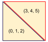
A vertex shader knows which (x, y) coordinates it has been assigned, so it could figure out which sections of coefficients it needs to access within the textures. But how would a vertex shader know which of the 6 blocks it should process? Solution: Misappropriate the vertex’s z coordinate. It’s not used for anything else in this case.
So I set all of that up. Then I hit a new roadblock: How to get the reconstructed Y, U, and V samples transported to the fragment shader? I have found that communicating between shaders is quite difficult. Texture memory? WebGL doesn’t allow shaders to write back to texture memory; shaders can only read it. The standard way to communicate data from a vertex shader to a fragment shader is to declare variables as “varying”. Up until this point, I knew about varying variables but there was something I didn’t quite understand about them and it nagged at me: If 3 different executions of a vertex shader set 3 different values to a varying variable, what value is passed to the fragment shader?
It turns out that the varying variable varies, which means that the GPU passes interpolated values to each fragment shader invocation. This completely destroys this idea.
Second Idea: Vertex Workhorse, Take 2
The revised pitch is to work around the interpolation issue by just having each vertex shader invocation performs all 6 block transforms. That seems like a lot of redundant. However, I figured out that I can draw a square with only 4 vertices by arranging them in an ‘N’ pattern and asking WebGL to draw a TRIANGLE_STRIP instead of TRIANGLES. Now it’s only doing the 4x the extra work, and not 6x. GPUs are supposed to be great at this type of work, so it shouldn’t matter, right?
I wired up an experiment and then ran into a new problem: While I was able to transform a block (or at least pretend to), and load up a varying array (that wouldn’t vary since all vertex shaders wrote the same values) to transmit to the fragment shader, the fragment shader can’t access specific values within the varying block. To clarify, a WebGL shader can use a constant value — or a value that can be evaluated as a constant at compile time — to index into arrays; a WebGL shader can not compute an index into an array. Per my reading, this is a WebGL security consideration and the limitation may not be present in other OpenGL(-ES) implementations.
Not Giving Up Yet: Choking The Fragment Shader
You might want to be sitting down for this pitch:
- Vertex shader only interpolates texture coordinates to transmit to fragment shader
- Fragment shader performs IDCT for a single Y sample, U sample, and V sample
- Fragment shader converts YUV -> RGB
Seems straightforward enough. However, that step concerning IDCT for Y, U, and V entails a gargantuan number of operations. When computing the IDCT for an entire block of samples, it’s possible to leverage a lot of redundancy in the math which equates to far fewer overall operations. If you absolutely have to compute each sample individually, for an 8×8 block, that requires 64 multiplication/accumulation (MAC) operations per sample. For 3 color planes, and including a few extra multiplications involved in the RGB conversion, that tallies up to about 200 MACs per pixel. Then there’s the fact that this approach means a 4x redundant operations on the color planes.
It’s crazy, but I just want to see if it can be done. My approach is to pre-compute a pile of IDCT constants in the JavaScript and transmit them to the fragment shader via uniform variables. For a first order optimization, the IDCT constants are formatted as 4-element vectors. This allows computing 16 dot products rather than 64 individual multiplication/addition operations. Ideally, GPU hardware executes the dot products faster (and there is also the possibility of lining these calculations up as matrices).
I can report that I actually got a sample correctly transformed using this approach. Just one sample, through. Then I ran into some new problems:
Problem #1: Computing sample #1 vs. sample #0 requires a different table of 64 IDCT constants. Okay, so create a long table of 64 * 64 IDCT constants. However, this suffers from the same problem as seen in the previous approach: I can’t dynamically compute the index into this array. What’s the alternative? Maintain 64 separate named arrays and implement 64 branches, when branching of any kind is ill-advised in shader programming to begin with? I started to go down this path until I ran into…
Problem #2: Shaders can only be so large. 64 * 64 floats (4 bytes each) requires 16 kbytes of data and this well exceeds the amount of shader storage that I can assume is allowed. That brings this path of exploration to a screeching halt.
Further Brainstorming
I suppose I could forgo pre-computing the constants and directly compute the IDCT for each sample which would entail lots more multiplications as well as 128 cosine calculations per sample (384 considering all 3 color planes). I’m a little stuck with the transform idea right now. Maybe there are some other transforms I could try.
Another idea would be vector quantization. What little ORBX.js literature is available indicates that there is a method to allow real-time streaming but that it requires GPU assistance to yield enough horsepower to make it feasible. When I think of such severe asymmetry between compression and decompression, my mind drifts towards VQ algorithms. As I come to understand the benefits and limitations of GPU acceleration, I think I can envision a way that something similar to SVQ1, with its copious, hierarchical vector tables stored as textures, could be implemented using shaders.
So far, this all pertains to intra-coded video frames. What about opportunities for inter-coded frames? The only approach that I can envision here is to use WebGL’s readPixels() function to fetch the rasterized frame out of the GPU, and then upload it again as a new texture which a new frame processing pipeline could reference. Whether this idea is plausible would require some profiling.
Using interframes in such a manner seems to imply that the entire codec would need to operate in RGB space and not YUV.
Conclusions
The people behind ORBX.js have apparently figured out a way to create a shader-based video codec. I have yet to even begin to reason out a plausible approach. However, I’m glad I did this exercise since I have finally broken through my ignorance regarding modern GPU shader programming. It’s nice to have a topic like multimedia that allows me a jumping-off point to explore other areas.
I’d like to stay ignorant of the matter but I vaguely remember that GPUs liked to operate on different input and output memory regions and had internal parallelism, so probably simple 1-D DCT shaders (for all 8 cases) applied twice would be enough, e.g. src -> hor transformed -< ver transformed -> out.
Also you can think of decoding VP4 on CPU instead ;)
Kostya’s hunch is right. You want to do what us 3D people do in post processing: ping-pong the data between two buffers.
That is, think 3 shaders:
1. X decode IDCT
2. Y decode IDCT
3. YUV to RGB
OpenGL lets you create “Framebuffer objects”, which permit you to do rendering to a texture. You can attach textures to FBOs, so
* Create your input, X-Decoded and Y-Decoded
* Create two FBOs, which let you write to the X-Decoded and Y-Decoded textures
Then, for each frame:
1. Bind the X-Decoded FBO, input texture, X decode shader, render a quad
2. Bind the Y-Decoded FBO, X decoded FBO texture, Y decode shader, render a quad
3. Unbind the FBOs (bind the screen), bind the Y decoded texture, YUV to RGB shader, render a quad
If you need to do any CPU processing for a non-I-frame, you’ll want to read back the FBO. If you can do it all on the GPU, then you might want another shader which will mix between the new input data and the YUV FBO
One option would be to have a second texture which contains control information for the decoder. You’re correct: GPUs are bad at branching, particularly older ones, so you generally have to do everything then use the mix() function with a value which is either 0 or 1 to pick between the two cases.
Oh, and if you were using OpenGL 4 or DirectX 11 I would say to use a compute shader (then you would be able to do one block, or one block slice at least, per invocation)
It was my understanding that ORBX.js does not *decode* using shaders, it *encodes* using shaders into a highly asymmetric format that is simple enough for javascript to decode on modern hardware.
Although, if that’s true, then the “You’re right that WebGL does heavy lifting.” comment is confusing.
@Kostya and Owen: Thanks to both of you. Your comments have given me a few more avenues to explore.
@Jim: I guess the whole thing is open to interpretation since they give so few specific details. The problem I find with encoding to a format that is simple enough for JS to decode is that their claims were that the format is “better” than H.264 which implies superiority on either the bitrate axis, the quality axis, or both (can’t remember how the available literature qualified the claims). I can’t think of a codec that fits that criteria AND can be decoded in real-time by JavaScript (I don’t even want to hear any claims about magical asm.js optimizations).
Another thought: block+global motion compensation
Global compensation would be passed to the shader as a vec2 uniform; that is relatively easy
Block motion compensation you’d probably want to decode into a Red-Green texture (of the dimensions of the video in blocks) and sample it in a shader to read out the block vectors (remembering to scale it appropriately). Of course you’d set the image you’re doing your compensation from to clamp at the edges.
You could let the GPU do its’ linear interpolation between the pixels of the block motion texture in order to smooth that out somewhat and avoid discontinuities, and of course you get subpixel sampling “for free”
You can probably offload enough of the processing to the graphics card to cope with JavaScript’s speed deficiencies
Vertex shaders are almost useless for GPGPU, as you discovered. Fragment shaders are where the real work happens, and most of the time you will just render a big quad the size of your output texture(s). The main way to think about GPGPU is that you get to produce a small number of outputs (up to 4 values per texture, up to 16 textures per fragment with Multiple Render Targets, though in practice most implementations don’t support that many) from arbitrarily arranged inputs (texture lookups) by running the same kernel (fragment shader) for every output. How data is packed into textures is arbitrary, and the texture coordinates of the output serve merely as an abstract index of which calculation to perform. Each texture lookup carries some overhead, and the texture cache is 2D, so you want adjacent fragments to be doing texture lookups from adjacent locations in both dimensions, if at all possible. Of course, you want 1000’s of fragments per pass to keep the GPU occupied.
You could do a full 8×8 iDCT as a single fragment program if you had support for 16 output textures (4*16=64 outputs). But in reality you may only have 4 or so (the spec actually mandates just 1), so focusing on 8-point 1-D -iDCTs is better.
These have 8 outputs, which requires 2 RGBA textures. So to actually get good performance, you’d want to arrange the passes Owen describes as follows:
1) In your de-zig-zag step, pack data so that every block column is stored in 2 RGBA texels, in two Wx(H/8) textures.
2) Perform column iDCTs by rendering a Wx(H/8) quad and outputting to two Wx(H/8) RGBA textures. This requires just two texture loads and two texture stores per 8 coefficients, and you get to use a fast 8-point iDCT.
3) Perform row iDCTs by rendering a (W/8)xH quad, storing each output row in two (W/8)xH RGBA textures. This requires eight loads (for the 8 columns that contribute to each row). Use the X coordinate of the output to select which texture to load from and which channel to use. Even though you only use 1/4 of the data you load, adjacent fragments will use the other values, so you make good use of the texture cache (the bottleneck is in the “memory -> texture cache” link, not the “texture cache -> fragment program” link). This is more texture loads than you’d like, and there is some overhead in doing the selection, but it should be small compared to the cost of the iDCT. Maybe someone else can think of a better way to structure this pass.
4) YUV->RGB: Render a WxH quad that loads each row from separate Y, Cb, and Cr textures, each processed with steps 1-3 above. Use the X coordinate to select which texture to load from and which channels to use in the actual conversion step.
In total you have (2+8)/8 + 3 = 4.25 loads/pixel and (2+2)/8 + 1 = 1.5 stores/pixel, and the actual iDCT is work-efficient (i.e., you’re not doing any more redundant math than you would in the serial version of the algorithm). There’s still a bit of redundancy in the YUV->RGB computation, since for 4:2:0 data you wind up re-computing the Cb and Cr parts four times, but that’s pretty normal.
Note that delta decoding *can* be parallelised (using the well-known parallel prefix sum), just that there’s no point in doing it for CPUs/GPUs since the fundamental operation (addition/subtraction) is so cheap and the blocks are small. FPGAs/ASICs are a different story.